
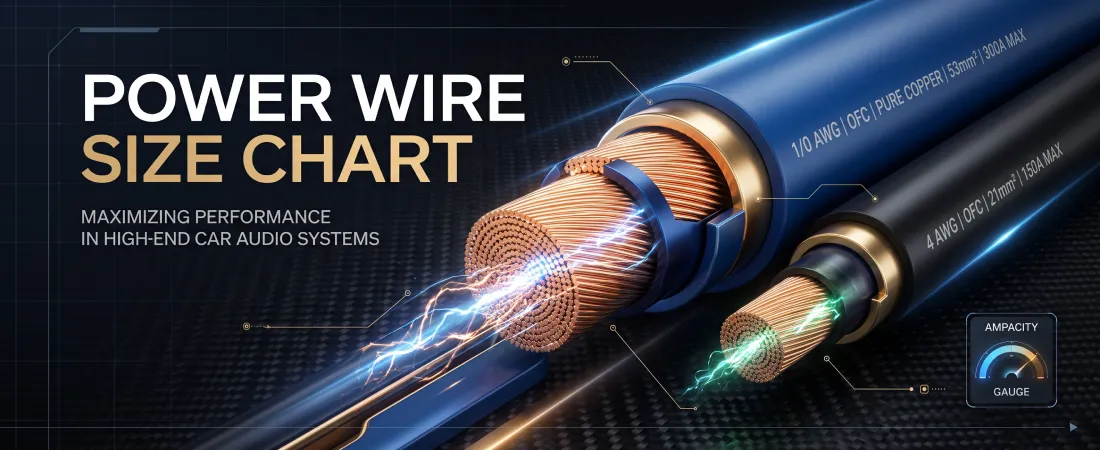
Selecting the correct power wire gauge is one of the most critical safety and performance decisions in car audio installation. An amplifier requires a steady supply of current from the vehicle’s electrical system to produce clean power. If the power wire is too small, electrical resistance generates excessive heat, causes severe voltage drops, limits amplifier output, and poses a serious fire hazard.
Wire sizing is determined by two main factors: total current draw (amperage) and the physical length of the cable run from the battery to the amplifier. Using an accurate American Wire Gauge (AWG) chart ensures your electrical delivery matches your system’s power demands.
American Wire Gauge (AWG) vs. Oversized & Metric Sizes
When purchasing car audio power wire, understanding wire standards is essential. In North America, the standardized measure for electrical conductor thickness is American Wire Gauge (AWG).
As AWG numbers decrease, the physical diameter of the copper conductor increases:
- 10 AWG / 8 AWG: Used for small multi-channel amplifiers or modest powered subwoofers.
- 4 AWG: The industry standard for mid-sized single or multi-amplifier builds (500 W to 1,200 W RMS).
- 1/0 AWG (Zero Gauge): Designed for high-power systems (1,500 W to 3,000 W RMS) requiring heavy current transfer.
- 2/0 AWG or Dual 1/0 AWG: Used in extreme competition builds pulling high current continuously.
Beware of Cheater Wire: Many budget brands sell wire labeled “4 Gauge” or “1/0 Gauge” that uses thick plastic insulation wrapped around a tiny core of wire. Always verify that the cable strictly complies with OFC (Oxygen-Free Copper) and AWG standards rather than non-standard “Gauge” sizing.
Copper Conductors: OFC vs. CCA
The physical material of the conductor directly alters how much current a wire can carry safely over distance:
- OFC (Oxygen-Free Copper): Constructed from pure copper (99.99% pure). OFC offers superior conductivity, lower internal electrical resistance, higher heat tolerance, and excellent resistance to corrosion in automotive environments.
- CCA (Copper-Clad Aluminum): Constructed from an aluminum core coated with a thin outer layer of copper. Aluminum has roughly 30% to 40% higher electrical resistance than copper. As a result, CCA wire gets hotter under load and requires a significantly larger gauge size to carry the same amperage as pure OFC.
For long-term reliability and maximum amplifier output, pure OFC wire is strongly recommended.
Recommended Wire Gauge Selection Chart (12V–14.4V Systems)
The following chart outlines the required AWG wire size based on continuous RMS current draw and wire run length for 100% Oxygen-Free Copper (OFC) power wire:
| Total Current Draw (Amps) | Approximate RMS Power @ 13.8V | 4 to 7 Feet Run | 7 to 10 Feet Run | 10 to 13 Feet Run | 13 to 16 Feet Run | 16 to 19 Feet Run |
|---|---|---|---|---|---|---|
|
0 – 20 A |
Up to 250 W |
10 AWG |
10 AWG |
10 AWG |
8 AWG |
8 AWG |
|
20 – 35 A |
250 W – 400 W |
8 AWG |
8 AWG |
8 AWG |
8 AWG |
6 AWG |
|
35 – 50 A |
400 W – 600 W |
8 AWG |
8 AWG |
6 AWG |
6 AWG |
4 AWG |
|
50 – 85 A |
600 W – 1,000 W |
6 AWG |
4 AWG |
4 AWG |
4 AWG |
4 AWG |
|
85 – 125 A |
1,000 W – 1,500 W |
4 AWG |
4 AWG |
4 AWG |
2 AWG |
2 AWG |
|
125 – 150 A |
1,500 W – 1,800 W |
4 AWG |
2 AWG |
2 AWG |
1/0 AWG |
1/0 AWG |
|
150 – 200 A |
1,800 W – 2,500 W |
2 AWG |
2 AWG |
1/0 AWG |
1/0 AWG |
1/0 AWG |
|
200 – 300 A |
2,500 W – 3,500 W |
1/0 AWG |
1/0 AWG |
1/0 AWG |
Dual 1/0 AWG |
Dual 1/0 AWG |
Note for CCA Wire: If using Copper-Clad Aluminum (CCA) wire, step up at least one full gauge size larger than indicated on the chart (e.g., use 1/0 AWG CCA where 2 AWG or 4 AWG OFC is listed).
To estimate voltage drop across custom wire runs and current loads, use our interactive voltage drop calculator.
How to Calculate Amplifier Current Draw
To determine which row on the chart applies to your installation, calculate your system’s maximum current draw (I) using continuous RMS power (P), supply voltage (V), and amplifier efficiency (η):
I = P / (V × η)
- Determine Total RMS Power (P): Sum the continuous RMS power output of all amplifiers in your system.
- Determine Supply Voltage (V): Use a realistic operating voltage of 13.8 V (representing a standard charging alternator).
- Account for Amplifier Efficiency (η):
- Class D Amplifiers: ~80% efficient (η = 0.80$).
- Class A/B Amplifiers: ~50% to 60% efficient (η = 0.50 – 0.60$).
Example Calculation:
I = 1000 13.8 × 0.80 = 1000 11.04 ≈ 90.57 Amps
Referencing the chart for a typical 16-foot run in a vehicle passenger cabin, 90.57 A requires 4 AWG OFC power wire.
Recommended Video Resources
How to Choose the Right Wire Gauge for Car Audio
This video demonstrates the physical differences between AWG and non-AWG power wire, explains voltage drop under heavy current loads, and illustrates OFC vs. CCA heating testing.
Car Audio Wire Sizing & Fusing Basics
An educational walkthrough showing how wire length and current draw determine power wire gauge and main battery fuse selection.
Common Mistakes
- Using CCA Wire at OFC Amperage Ratings: Expecting Copper-Clad Aluminum wire to handle the high current capacity of pure copper results in high resistance, excessive heating, and blown inline fuses.
- Buying Non-AWG “Trick” Wire: Purchasing cheap wiring kits with thick plastic jackets that conceal undersized interior conductors.
- Ignoring Distance in the Calculation: Sizing wire solely on current draw without considering the total length of the cable run from battery to trunk.
- Mismatched Ground Wire Gauge: Running a thick 1/0 AWG power wire from the battery but grounding the amplifier with a thin 4 AWG or 8 AWG wire. Ground wire must always match or exceed the power wire size.
- Failing to Protect Wire Pass-Throughs: Running heavy power cable through sheet metal firewalls without a rubber grommet, leading to insulation abrasion and direct short circuits.
References
- Crutchfield Learning Center – Car Audio Wire Gauge Chart & Selection Guide
- Sonic Electronix Knowledge Base – What is Polyfill and Why Should I Use It?
- JL Audio School of Sound – Understanding Electrical Resistance, Current Draw, and Conductors