
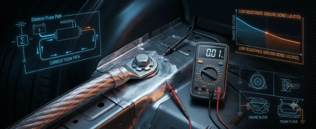
Grounding is one of the most critical yet frequently overlooked aspects of a car audio installation. Every watt of electrical power delivered from your battery and alternator to an amplifier must complete a return path back to the vehicle’s charging system through the chassis.
A weak or improper ground introduces electrical resistance, causing severe voltage drops, amplifier protective shutdowns, overheating, and annoying alternator whine in your speakers. Following proper grounding techniques ensures maximum power delivery, optimal sound quality, and long-term equipment reliability.
Why the Ground Path Matters
Electrical current in a vehicle operates in a closed loop. The positive cable carries current from the battery and alternator to your audio equipment, but that current cannot flow unless it has an equally capable path back to the power source.
In modern vehicles, the metal unibody or structural frame serves as the return conductor. If the connection between your amplifier’s ground wire and the vehicle’s chassis has high electrical resistance, current flow is restricted across the entire system.
According to Ohm’s Law, electrical resistance along the return path directly causes voltage loss:
ΔV = I · R
When an amplifier draws high current (I) through a restrictive ground connection (R), significant voltage (ΔV) is lost before reaching the internal power supply. This deprives the amplifier of continuous RMS power and forces the power supply to generate excessive heat.
To learn more about how electrical current flows through audio systems, read our guide on electrical system fundamentals.
Core Principles of a Solid Chassis Ground
Creating a reliable chassis ground requires strict adherence to physical and electrical installation standards:
1. Bare Metal Contact
Vehicle bodies are painted and treated with anti-corrosion primers at the factory. Paint, primer, and rust act as electrical insulators. You must grind or sand the contact location down to shiny, bare metal using sandpaper or a wire wheel before attaching ring terminals.
2. Solid Structural Frame Selection
Always connect your ground to a heavy structural frame member or floor pan strut. Avoid grounding to thin sheet metal panels, un-welded brackets, trunk lids, or hatch doors, as these panels often lack a direct structural connection to the main chassis.
3. Short Wire Length and Matching Gauge
Keep your ground cable as short as possible – ideally 18 inches to 3 feet in length. Longer wire runs add linear conductor resistance. Furthermore, your ground cable must always match or exceed the gauge size of your main positive power cable. Consult our power wire size chart to verify cable requirements.
4. Heavy-Duty Mechanical Fastening
Never rely on small sheet metal screws, which loosen over time from vehicle vibration. Use a heavy nut-and-bolt assembly with star washers, a factory chassis grounding stud, or a threaded rivet nut (nut-sert) cranked down tightly to maintain constant physical tension.
Testing Ground Quality with a Multimeter
Visual inspection alone cannot guarantee a low-resistance ground connection. You must verify electrical continuity using a Digital Multimeter (DMM):
- Set your multimeter to the resistance Ω setting.
- Place one probe on your prepped ground terminal location and the other probe on a known bare-metal reference point or the negative battery terminal.
- The measured resistance should ideally read under 0.2 ohms.
Alternatively, test for voltage drop under heavy system load. Place your multimeter leads across the amplifier’s positive and negative terminals while playing loud music. If voltage sags significantly at the amplifier while remaining stable at the battery, a restrictive ground path is likely the cause. Learn more in our article on voltage drop explained.
Recommended Video Resources
How to Properly Ground a Car Amplifier
This tutorial demonstrates good and bad grounding examples in a demo vehicle, showing how loose connections and un-sanded paint cause amplifier protect modes.How to Find and Test the Best Chassis Ground
A practical guide on using a multimeter to locate low-resistance grounding points, prepare bare metal surfaces, and seal connections against rust.
Common Mistakes
- Grounding Over Paint or Primer: Attaching ring terminals over painted surface areas creates high contact resistance, causing severe voltage drop under load.
- Using Small Sheet Metal Screws: Tapping thin screws into sheet metal leads to loose, vibrating connections that arc and degrade over time.
- Using Undersized Ground Cable: Installing a ground wire that is smaller in gauge than the positive power wire restricts current return flow.
- Grounding to Moving or Isolated Panels: Bolting ground terminals to trunk lids, door frames, or un-bonded brackets starves the circuit of a direct chassis path.
- Leaving Exposed Metal Unsealed: Failing to apply clear coat, dielectric grease, or undercoating after bolting down ring terminals invites moisture and rapid surface oxidation.
References
- Sonic Electronix Learning Center – How to Create a Proper Ground
- Crutchfield Articles & Videos – Amplifier Grounding & Installation Guide
- JL Audio School of Sound – Understanding Audio Fundamentals and Amplifier Loads