
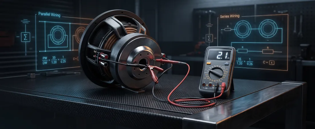
In car audio, wiring your subwoofers is more than just connecting wires to terminals. It is a critical electrical calibration that dictates how much power your amplifier can safely produce. Connecting subwoofers incorrectly can either severely limit your volume or destroy your amplifier by forcing it to operate below its stable limits.
To find the correct wiring configuration, you need to understand how the number of subwoofers, their voice coil types, and their individual resistance ratings combine to create a final electrical load. This guide translates the math behind subwoofer wiring into a simple, step-by-step framework to ensure a safe and powerful installation.
Phase 1: Identifying Your Components (The Inputs)
Before calculating your final ohm load, you must identify three key specifications of your hardware:
- Subwoofer Quantity: How many individual drivers are you installing in the enclosure?
- Voice Coil Type: Are your subwoofers Single Voice Coil (SVC) or Dual Voice Coil (DVC)?
- Coil Impedance: What is the electrical resistance of each individual voice coil (typically 1 ohm, 2 ohms, or 4 ohms)?
This information is usually printed directly on the subwoofer’s magnet assembly. If you are mixing subwoofers of different sizes, brands, or impedances, stop immediately – systems must use identical subwoofers to prevent uneven power distribution and phase cancellation.
Phase 2: The Core Math (Series vs. Parallel)
Subwoofer systems are wired using two primary circuit configurations, which manipulate electrical resistance in opposite directions as explained in our Series vs. Parallel Wiring Guide.
Series Wiring (Ohms Go Up)
In a series wiring configuration, electrical current flows along a single continuous path. The positive terminal of the amplifier connects to the positive terminal of the first voice coil, the negative of that coil connects to the positive of the next coil, and the final negative returns to the amplifier. Because electricity must flow through each resistor sequentially, the resistance values add together:
Rtotal = R1 + R2 + R3 + …
Parallel Wiring (Ohms Go Down)
In a parallel wiring configuration, the electrical current is divided into multiple parallel paths. The positive terminals of all voice coils are connected together and run to the amplifier’s positive terminal, while all negative terminals are connected together and run to the amplifier’s negative terminal. Because the electricity has more pathways to travel, the total resistance drops. For identical coils, the formula is:
Rtotal = RN
(Where R is the impedance of a single coil, and N is the total number of coils connected in parallel).
Phase 3: Common Configuration Chart
This reference chart outlines the most common configurations for monoblock amplifiers using identical subwoofers:
Warning: A 0.5-ohm final load is highly unstable and will damage most standard amplifiers. Always verify your amplifier’s minimum stable impedance (usually 1 ohm or 2 ohms for monoblocks) in the manual before executing parallel configurations.
Phase 4: Matching the Calculator to the Amp
Once you determine the possible wired configurations, you must match them to your amplifier’s power output stage:
- Mono Amplifiers (Class D): Typically optimized to produce maximum power at lower impedance loads, such as 1 ohm or 2 ohms. For a dual-subwoofer system, wiring in parallel to drop the load to 1 ohm or 2 ohms is often preferred to get the most wattage out of the amp.
- Multi-Channel Amplifiers (Bridged): When bridging channels together to power a subwoofer, the minimum stable impedance limit usually rises to 4 ohms. Running a 2-ohm or 1-ohm load on bridged channels will cause thermal overload, forcing the amplifier into protection mode.
For deeper instructions on setting your limits, read our comprehensive Ohms and Impedance guide.
Recommended Video Resources
Subwoofer Wiring: Series vs. Parallel Explained
Explains how different subwoofer wiring configurations impact back-EMF, phase behavior, and overall amplifier performance.
How To Wire Subwoofers – Parallel vs. Series
A practical, step-by-step tutorial showing physical connections, circuit layouts, and calculations for both SVC and DVC setups.
Common Mistakes
- Ignoring the Minimum Ohm Stability Limit: Wiring subwoofers down to a 1-ohm parallel load on an amplifier that is only stable down to 2 ohms. This forces the power supply to overheat, causing immediate protective shutdown or component failure.
- Leaving Voice Coils Disconnected on DVC Subs: Disconnecting half of a DVC subwoofer to make the impedance calculation easier. This drastically alters the subwoofer’s mechanical characteristics, raising the Q-factor (Qts) and making the bass sound muddy and uncontrolled.
- Bridging an Amp below Safe Impedance: Connecting a 2-ohm subwoofer load to a bridged 2-channel amplifier when its manual states a minimum bridged requirement of 4 ohms.
References
- Crutchfield Learning Center – Subwoofer Wiring Diagrams and Reference Guides
- MTX Audio Library – Calculating Subwoofer Impedance and Electrical Formulas
- Rockford Fosgate Support – Interactive Woofer Wiring Wizard