
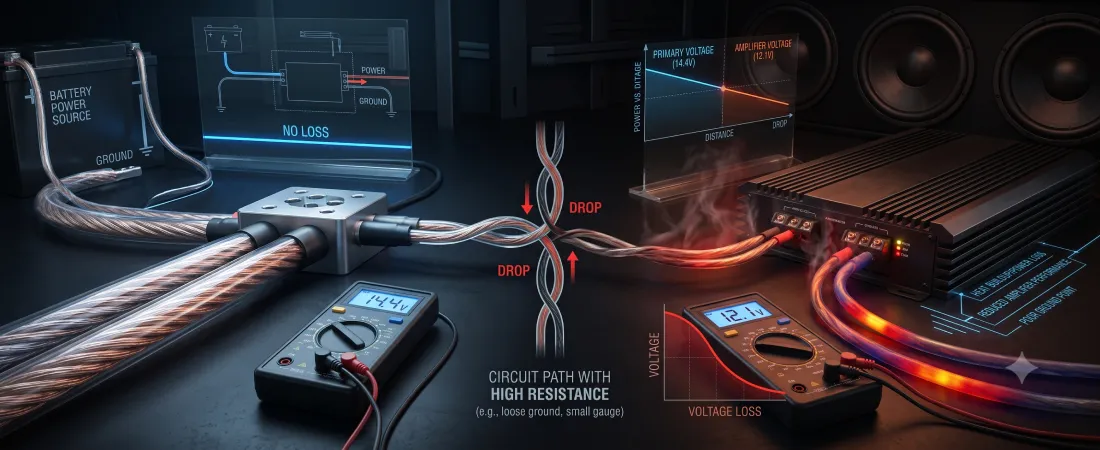
Voltage drop is one of the most common yet misunderstood problems in automotive sound systems. When an amplifier demands electrical current, any resistance along the power or ground path reduces the electrical potential reaching the amplifier terminals.
Understanding why voltage drop occurs and how to prevent it is essential for maintaining clean audio output, preventing amplifier shutdown, and protecting your vehicle’s electrical components.
What Is Voltage Drop?
In car audio, voltage drop refers to the reduction in electrical potential along a circuit as current flows from the battery and alternator to your audio equipment. Modern vehicle charging systems typically supply between 13.8 volts and 14.4 volts DC while the engine is running.
However, as current moves through power cables, fuses, and chassis grounds, electrical resistance consumes a portion of that energy as heat, lowering the available voltage at the amplifier.
The mathematical relationship governing voltage drop is defined by Ohm’s Law:
ΔV = I · R
In this equation, ΔV represents voltage drop, I is current in amperes drawn by the load, and R is resistance in ohms. As an amplifier draws more current to produce loud music passages, the voltage lost across the wiring increases proportionally.
According to industry standards such as ANSI/CTA-2031, the maximum allowable voltage drop across the main power wiring circuit should not exceed 0.25 volts under full rated load. Exceeding this limit deprives your amplifiers of the stable power required to deliver their rated continuous RMS output.
To understand the core foundation of vehicle power delivery, review our guide on electrical system fundamentals.
What Causes Voltage Drop in Car Audio?
Voltage drop is rarely caused by a single failing part; rather, it is the cumulative result of electrical restriction across the entire circuit. To diagnose voltage drop, you must examine how key factors restrict current flow:
- Undersized Wire Gauge: Running thin power or ground cable restricts current movement. Factory cables in many vehicles are sized only for base OEM electronics, typically equivalent to 6 AWG or 8 AWG wire.
- High Resistance Grounds: Grounding an amplifier to painted, rusted, or dirty metal creates high contact resistance, causing severe voltage loss on the return path.
- Excessive Cable Length: Electrical resistance increases linearly with cable length. Long wire runs from the engine bay to the trunk naturally introduce greater resistance.
- Charging System Deficits: Stock alternators generally produce 80 to 120 amperes. A 2,000-watt RMS system can demand 190 amperes at full output, overwhelming stock alternators and pulling system voltage down.
Symptoms of Excessive Voltage Drop
When voltage sags severely under heavy audio loads, your system displays several clear warning signs:
- Headlight Dimming: Vehicle headlights, interior lights, or dashboard displays flicker or dim in sync with heavy bass notes.
- Amplifier Protection Mode: Amplifiers suddenly shut down or cut out during loud playback due to low voltage.
- Audio Distortion and Muddy Bass: Low voltage forces amplifier power supplies to clip, producing harsh distortion and poor bass response.
- Excessive Component Heat: Unregulated power supplies draw higher current to compensate for lower voltage, causing severe heat buildup.
How to Fix and Prevent Voltage Drop
Eliminating voltage drop requires a systematic approach to reducing electrical resistance throughout the entire power path.
1. Upgrade Main Cable Gauges
Installing properly sized, high-strand 100% Oxygen-Free Copper (OFC) wiring drastically reduces conductor resistance. For systems exceeding 1,000 watts RMS, 1/0 AWG OFC wire is the standard choice. Consult our power wire size chart to select the correct cable gauge for your current requirements.
2. Execute Proper Grounding Practices
Always ground your equipment to a solid structural frame or chassis member. Sand the contact area down to bare, shiny metal to remove paint and rust before bolting down ring terminals. For detailed instructions, read our guide on grounding best practices.
3. Perform the Big 3 Upgrade
The Big 3 upgrade replaces or supplements three restrictive factory cables under the hood with heavy-gauge 1/0 AWG OFC wire:
- Alternator positive to battery positive
- Battery negative to chassis ground
- Engine block to chassis ground
4. Balance Charging Output and Load
If your system’s total current draw exceeds your alternator’s rated output, upgrading to a high-output alternator ensures continuous power delivery. Learn more in our article on alternators and audio load, or calculate expected losses using our voltage drop calculator.
Recommended Video Resources
How to Measure Voltage Drop & Test Amplifier Grounds
This video demonstrates step-by-step how to use a digital multimeter to locate resistance bottlenecks and measure voltage drop across power cables and chassis ground connections.
How To Install the Big 3 Upgrade
An in-depth tutorial demonstrating how upgrading factory under-hood wiring eliminates charging system bottlenecks and stabilizes system voltage under heavy audio loads.
Common Mistakes
- Blaming the Alternator First: Replacing an alternator without fixing undersized or corroded wiring will not resolve voltage drop.
- Using Copper-Clad Aluminum (CCA) Wire: CCA wire has significantly higher resistance than pure Oxygen-Free Copper (OFC), leading to greater voltage sag.
- Grounding Over Paint: Attaching ground terminals over painted metal creates massive contact resistance on the return circuit.
- Skipping the Engine Block Ground: Neglecting the engine-to-chassis ground starves the alternator return path, as alternators ground through the engine case.
References
- Sonic Electronix Learning Center – What Gauge Wire is needed for my Amplifier?
- Crutchfield Learning Center – Amplifier Wire Gauge Chart & Power Delivery
- JL Audio School of Sound – Understanding Audio Fundamentals and Amplifier Loads