
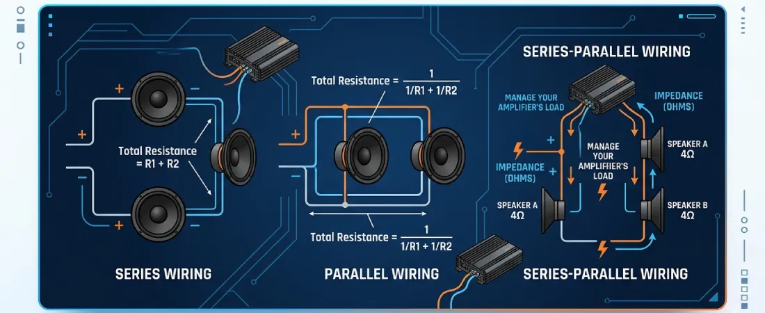
When installing multiple subwoofers or configuring a dual voice coil driver, the way you connect the speaker wires determines the electrical resistance the amplifier “sees.” This electrical resistance is called Impedance. Connecting subwoofers incorrectly can either choke your amplifier’s power output or force the amplifier to run below its stable limits, leading to overheating and thermal failure. Understanding the differences between series and parallel wiring is the key to matching your subwoofer configuration to your amplifier’s safe operating sweet spot.
Phase 1: Series Wiring (Adding Resistance)
In a series wiring configuration, electrical current flows along a single continuous path. The positive terminal of the amplifier connects to the positive terminal of the first voice coil, the negative of that coil connects to the positive of the next coil, and the final negative returns to the amplifier.
Because the electricity must pass through each coil sequentially, the total electrical resistance increases. To calculate the total impedance ($R_{total}$) of loads wired in series, you simply add the individual resistance values together:

- Example: Wiring two single-voice-coil (SVC) 2-ohm subwoofers in series presents a total load of 4 ohms to the amplifier.
- System Impact: Series wiring is typically used to raise the overall impedance to make a speaker load compatible with bridging a multi-channel amplifier, which often requires a minimum load of 4 ohms.
Phase 2: Parallel Wiring (Dividing Resistance)
In a parallel wiring configuration, the electrical current is divided into multiple parallel paths. The positive terminals of all voice coils are connected together and run to the amplifier’s positive terminal, while all negative terminals are connected together and run to the amplifier’s negative terminal.
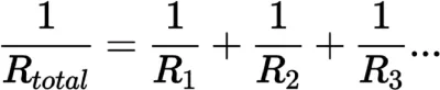
Because the current has more pathways to travel, the overall resistance to the flow of electricity is reduced. The formula for calculating the total resistance of loads in parallel is:
If all the subwoofers have the identical impedance (which is a strict requirement for system balance), you can use this simplified shortcut where $R$ is the impedance of a single voice coil and $N$ is the total number of coils:
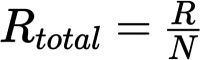
- Example: Wiring two 4-ohm subwoofers in parallel drops the total impedance to 2 ohms.
- System Impact: Parallel wiring is the standard method for drawing maximum power from monoblock (single-channel) amplifiers, which are often designed to produce their peak wattage at a 1-ohm or 2-ohm stable load.
Phase 3: Series-Parallel Wiring (The Hybrid Approach)
For complex systems—such as installing multiple Single Voice Coil (SVC) or Dual Voice Coil (DVC) subwoofers—installers use a combination of both wiring styles to reach a target impedance. This is called series-parallel wiring.
For example, if you have a pair of dual 4-ohm voice coil subwoofers and a monoblock amplifier that is 4-ohm stable, you cannot wire everything in parallel (which would create an unstable 1-ohm load). Instead, you wire the dual voice coils of each individual subwoofer in series (creating two 8-ohm loads), and then wire those two subwoofers in parallel with each other back to the amplifier. This returns the total load to a perfectly safe 4 ohms.
Phase 4: System Stability and Safe Calibration
Before turning on your system, you must verify that the total impedance matches your amplifier’s capabilities. Always match your continuous power requirements by reading the RMS vs Peak Power specifications of your components to ensure you do not overdrive the voice coils.
- Under-impeding: Wiring subwoofers to a total resistance lower than what the amplifier is rated for (e.g., creating a 1-ohm load on a 2-ohm stable amplifier) forces the power supply to push too much current. This triggers protect mode or causes thermal failure.
- Over-impeding: Wiring to an impedance that is too high (e.g., an 8-ohm load on an amp optimized for 2 ohms) is safe, but it significantly reduces the output power of your system.